Maliy pr. V. O., 62/2, liter A, St. Petersburg, Russian Federation, 199178
Cutting mill CM 120M


|
INDUSTRIES
|
APPLICATIONS Bismuth telluride, carbon fiber, PVC, polyester resin, ABS plastic, CDs, SIM cards, nanotubes, collagen, rubber, jute, PAN fiber, fabric, cotton, rubber, silicone, wax, bark, chicory, dried mushrooms, tea
|


CHARACTERISTICS
|
TECHNOLOGICAL PARAMETERS |
|
| Average product particle size when installing a grate with minimum openings, mm | 0,2-0,4 |
| Product particle size when installing a grate with minimum openings, mm | 90%<0,5 |
| Maximum initial material grain size, mm* | 50 |
| Output, kg/hour** | 2-100 |
| TECHNICAL PARAMETERS | |
| Mill loading door dimensions, mm | 60х80 |
| Size of discharge grate openings, mm | 0,8-20 |
| 50 Hz supply voltage, V | 220/380 |
| Electric motor power, kW | 1,5/1,1 |
| Rotor speed, rpm | 1500 |
| Gross/usable capacity of the collecting container, l | 1,8/1,2 |
| Overall dimensions (Length x Width x Height), mm | 500х380х685 |
| Weight/weight with control panel, kg | 48/- |
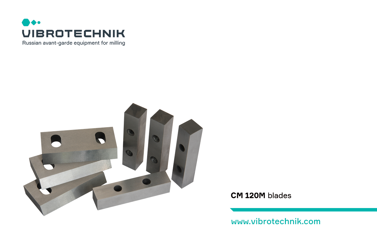
| Blades material – tool steel | 105WCr6, 90CrSi, 41Cr4 |
| Blades hardness, HRC | 40-45 |
| Compatible control panel | CCPB-10/CCPB-4,0 (built-in) |
* It is possible to batch load materials of an elongated shape, the size of which in one of the dimensions significantly exceeds the specified
** Depends on the physical properties of the material and the size of discharge grate openings
ADVANTAGES
 |
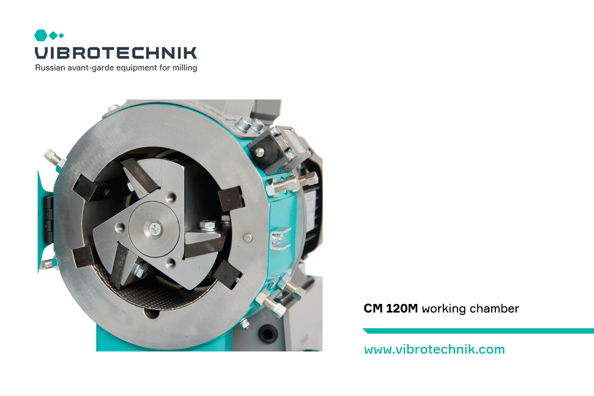
MILLING EFFICIENCY The accuracy of setting the gap between the casing blades and the rotor blades provides shear deformation during grinding. PRODUCT PARTICLE SIZE AJUSTMENT There are 3 ways to adjust the particle size of the product:
OPERATIONAL SAFETY The end switch excludes start-up with open milling chamber and automatically cuts off the power supply to the electric motor when the cover is opened. The shock absorbers reduce the vibration transmitted to the bearing surface. LABORATORY APPLICATION Due to its small size and low energy consumption, CM 120M is suitable for use in laboratories. |
|
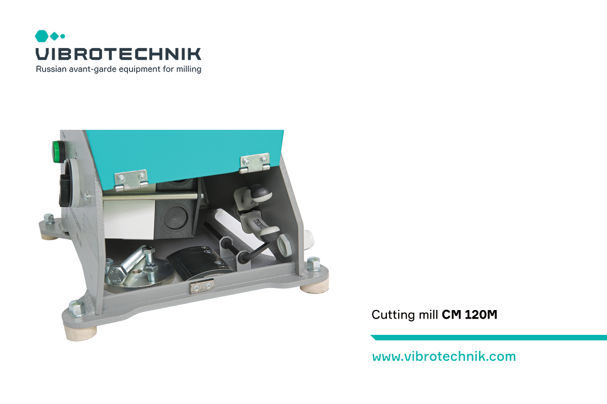
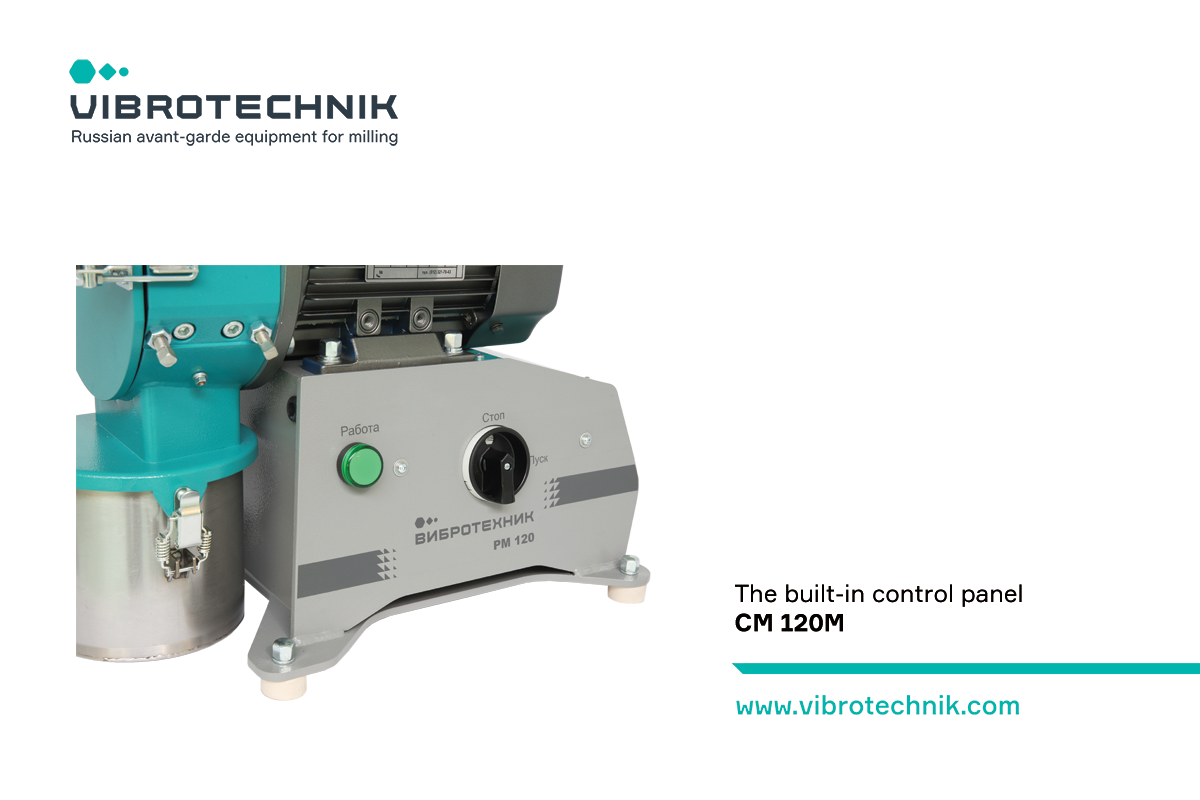
COMPACTNESS The new base allows installing the mill on a table or a stand. There is a cavity in the base to store accessories: blades template, rotor puller, thin-nose pliers. CM 120M has a compact built-in control panel. |
 |
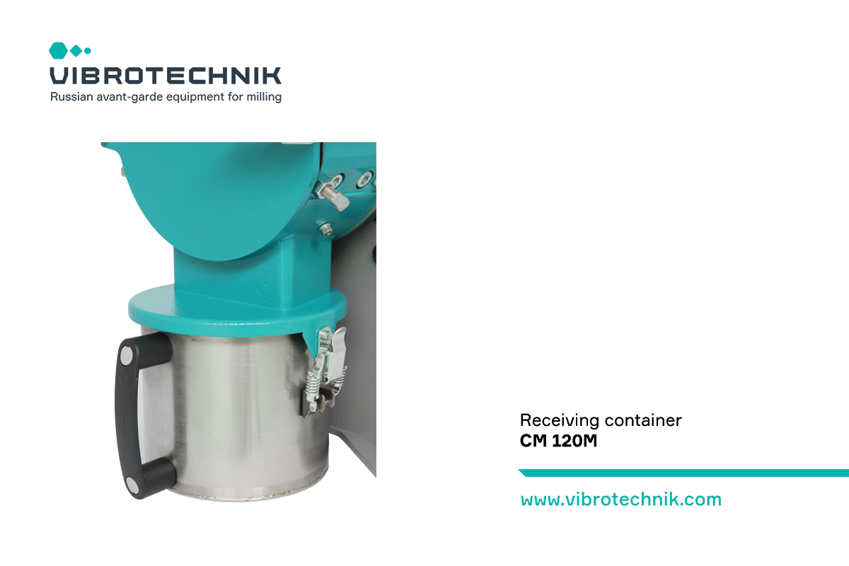 |
COLLECTING CONTAINER CM 120M is equipped with the quick-detachable collecting container of 2 liters. A rubber seal of the discharge funnel reduces dust during operation. Installation of a special nozzle for continuous unloading instead of standard collecting container is possible. |
|
BUILT-IN CONTROL PANEL The built-in control panel is designed to start and stop the mill and provides:
|
 |
 |
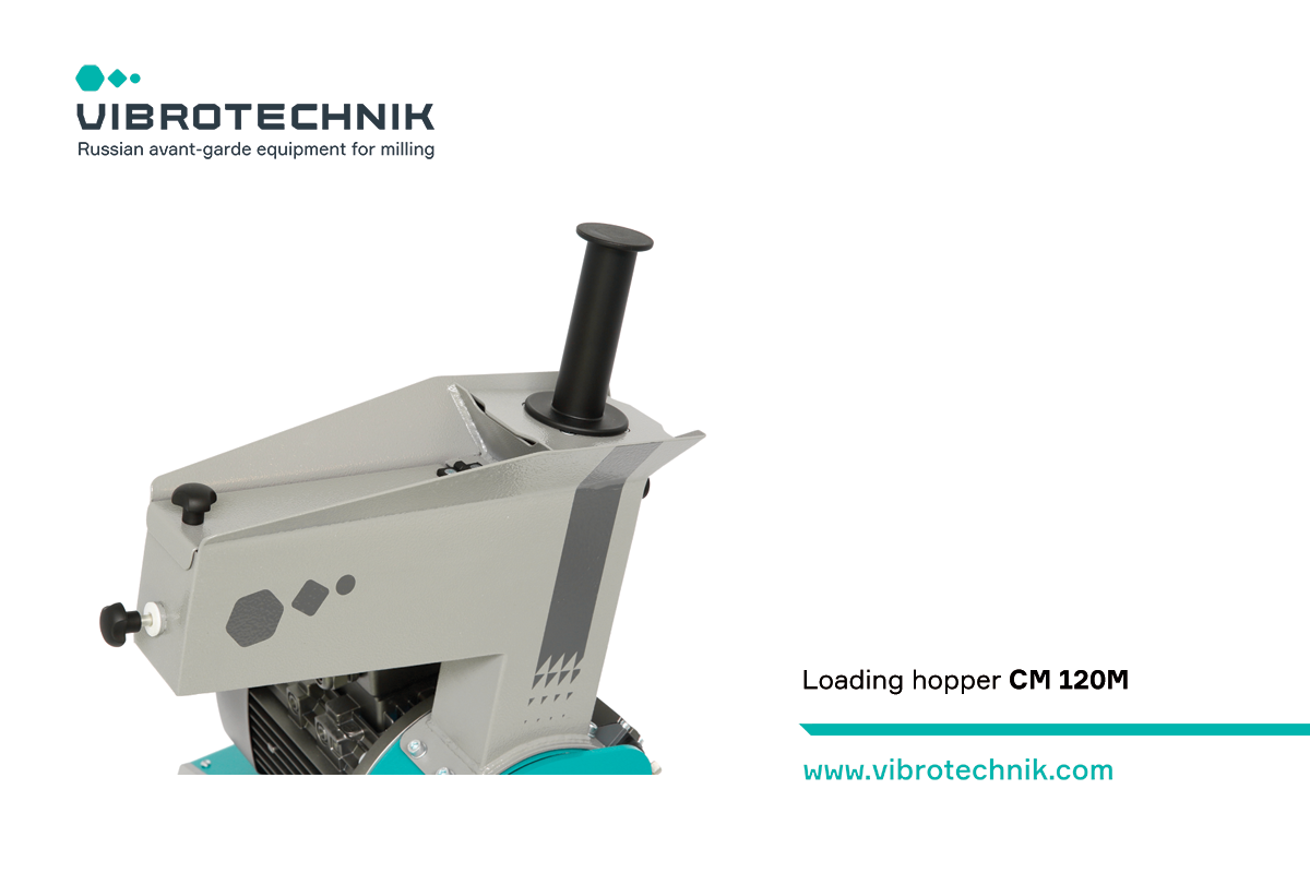
LOADING FUNNEL Easy loading of loose and fiber materials:
The vertical shaft provides the convenience of loading fiber materials. The hopper lid eliminates material ejection during the operation. |
|
HIGHER RESOURCE Increased service life of blades due to replacing of the casing blades and sharpening of rotor blades. |
 |
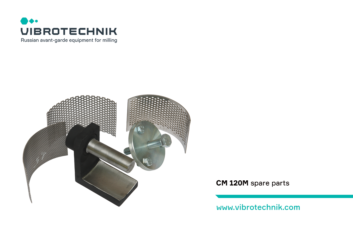 |
QUALITY SPARE PARTS Knives are made of hardened tool steel. Discharge grates are made of stainless steel. CM 120M is equipped with blades template, rotor puller, thin-nose pliers. |
DESCRIPTION OF THE DEVICE
|
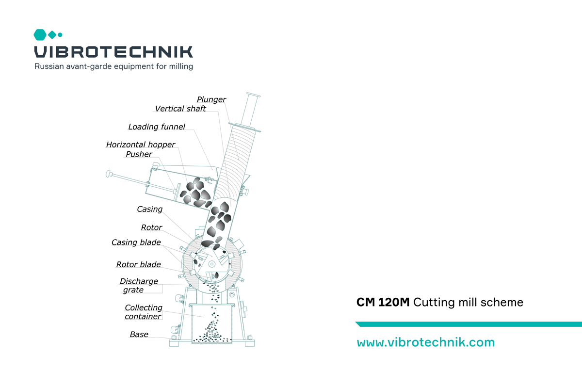
In a cutting mill, comminution occurs due to cutting — shear deformations. The structure of CM 120M cutting mill includes: a loading funnel, a casing with fixed blades, a rotor with moving blades, a discharge grate, an unloading funnel, a base and an electric motor. An electric motor is installed on the base, to the flange of which a hollow cylindrical body is attached. In the upper part of the housing there is a loading funnel. It consists of a vertical shaft with a plunger and a horizontal hopper with a pusher. In the lower part of the body, a discharge grate is installed. The size of grate openings determines the size of the product particles The milling chamber formed by the inner surface of the casing and the motor flange is locked by the front cover. Inside the milling chamber there is a rotor and seven blades: four fixed on the casing and three moving blades on the rotor. OPERATING PRINCIPLE The material fed through the loading funnel into the milling chamber. Milling (cutting) of the material occurs when particles enter between the casing blades and the rotor blades. The milled material passes through the openings of the discharge grate and enters the unloading funnel. PRODUCTION OPTIONS
SPECIAL OPTIONS:
|
CM 120M Cutting mill scheme Loading hopper CM 120M milling chamber 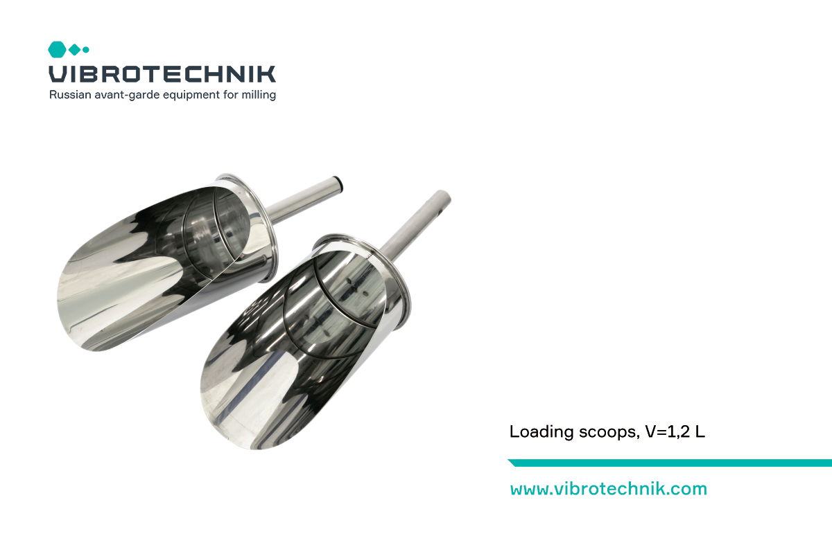
Loading scoops, V=1,2 L |